Blade grinding jig
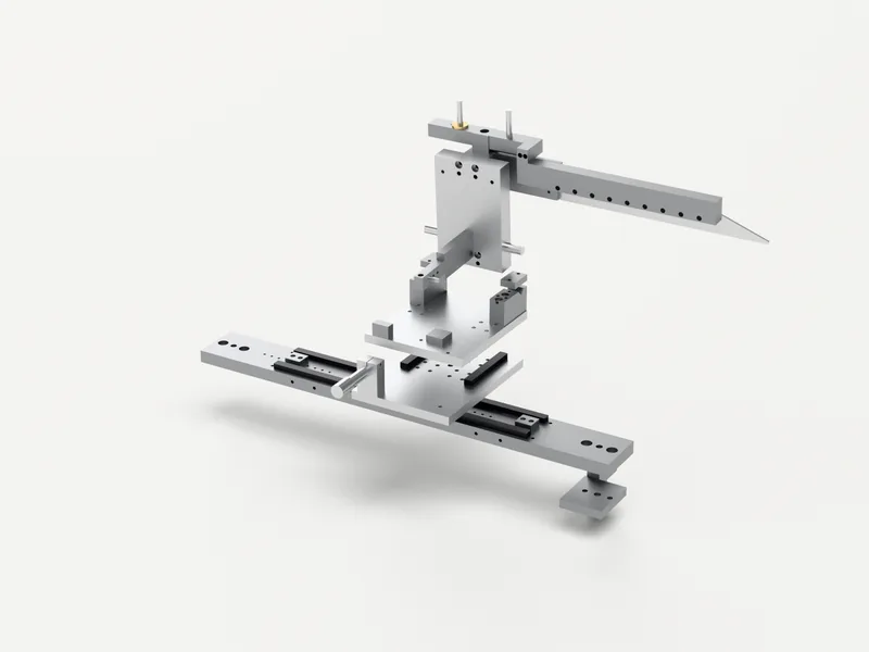
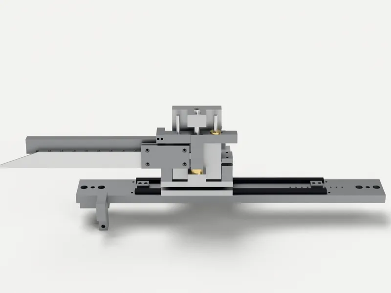
A precision jig for a Burr King 960 belt grinder, designed to put repeatable bevels on blades up to 300 mm.
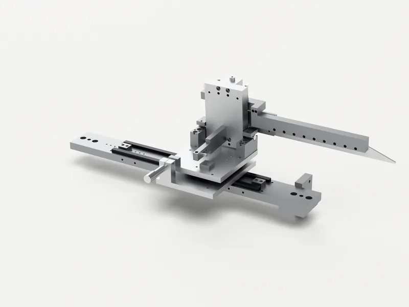
Bevel angle set to about 0.001° with a gauge stack, on a $165 to $215 budget.
- Scope
- Design, drawings and bill of materials
- Tools
- SOLIDWORKS, interference studies
- Size
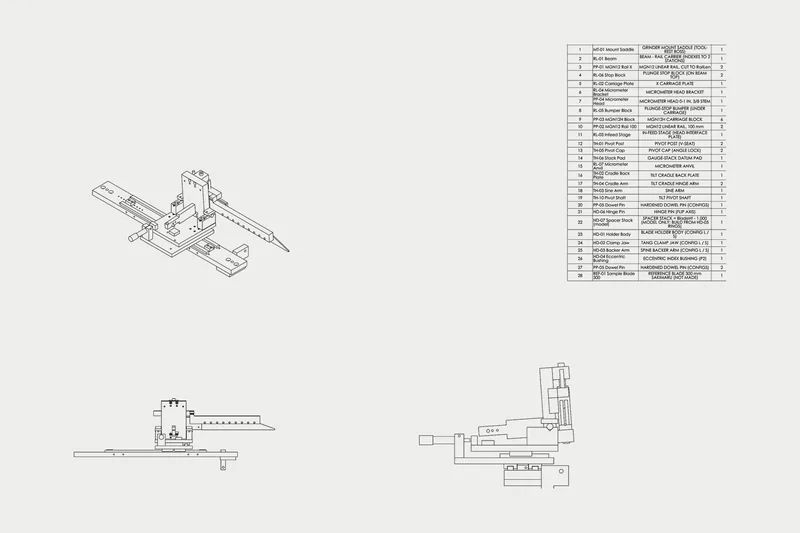
- 22 manufactured parts, 137 mates
Freehand bevels don’t scale to 300 mm
Grinding a bevel freehand gets harder with every inch of blade. On a 300 mm knife, small changes in angle or pressure show up as a wavy grind, and getting both sides to match is harder still.
I wanted the bevel angle to be something you set and measure, not something you feel, on a budget that doesn't assume a surface grinder.
Set the angle like a sine bar
The angle is set the way a sine bar sets one. A 5.000 inch arm rests on a gauge stack, so h = 1.000 − 5.000 sin θ, and a 0.0001 inch change in the stack moves the angle about 0.001°. Capped V-seats then lock the shaft.
Covering both sides of a blade would take a 41 inch rail, so one 16.4 inch stroke is used twice by re-pinning the whole beam at a second station.
Drawn, costed and ready to cut
The design is drawn and costed but not yet cut. It covers 22 manufactured parts in 1018 steel, 6061 aluminum, O1 drill rod and C360 brass, on MGN12 rails with a micrometer in-feed.
Accuracy comes from machining order: the holder's datum face and hinge bore are cut in one setup so both sides match, and both V-seats are milled in one pass so the tilt axis is straight.
Checked in CAD, not yet in steel
In CAD, all 29 parts rebuild fully defined and the 137 mates check out against their target poses. An interference sweep across both stations, 0.5° to 10° and 1 to 2 inch blade heights found only the intended press fits.
Before cutting metal, the grinder mount needs checking against the real machine, since it was modeled from photos.
I had never used AI for CAD before and wanted to try it on a project that would actually be useful. I wrote out a very extensive prompt about the assembly I wanted made, including how it should function, all the design limitations (material, price, function and accuracy), the dimensions of where it attaches to the grinder, and how I wanted the design to be constrained. Overall, it gave me a pretty decent baseline to work from, and things were actually constrained properly.
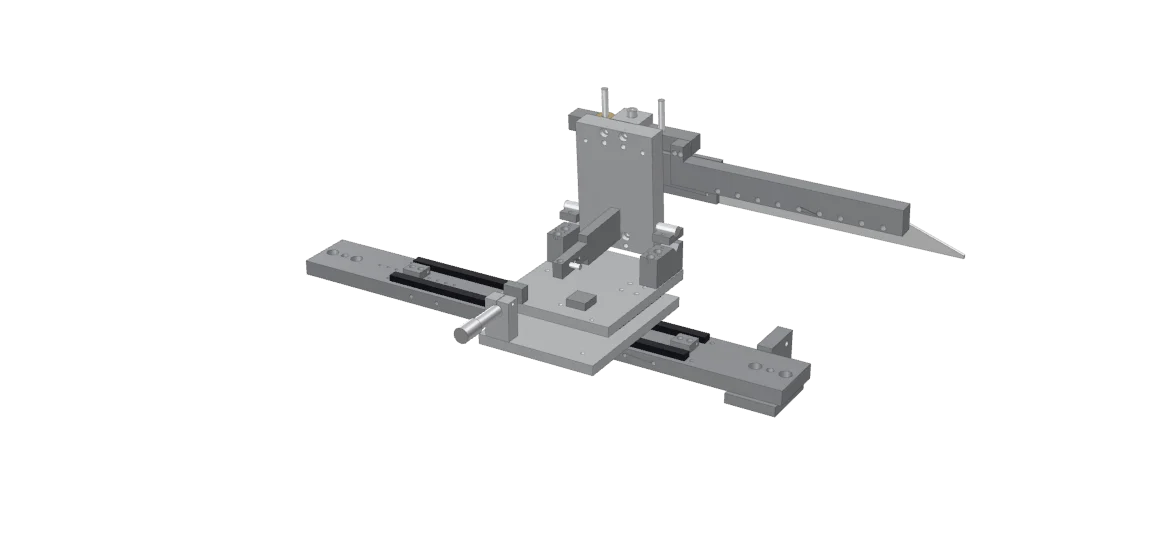
Parts list
- MT-01 Mount saddle
- MGN12 rail, in-feed× 2
- MGN12H carriage block× 6
- Micrometer head
- RL-02 Carriage plate
- RL-04 Micrometer bracket
- RL-05 Stop bumper
- RL-03 In-feed stage
- RL-07 Micrometer anvil
- HD-04 Eccentric bushing
- REF-01 Sample blade, 300 mm
- HD-06 Hinge pin
- HD-05 Spacer ring stack
- Dowel pin× 3
- HD-01 Holder body
- HD-02 Clamp jaw
- HD-03 Spine backer arm
- TH-02 Cradle back plate
- TH-03 Sine arm
- TH-04 Cradle hinge arm× 2
- TH-10 Pivot shaft
- TH-01 Pivot post× 2
- TH-05 Pivot cap× 2
- TH-06 Stack pad
- MGN12 rail, X travel× 2
- RL-01 Beam
- RL-06 Plunge stop block× 2