Direct-drive sim wheel
A force-feedback racing wheel built around a hoverboard hub motor, developed through three design generations.
About 12 Nm of direct-drive force feedback for about $100.
- Role
- Design and build
- Tools
- SOLIDWORKS, machine shop, FDM printing
- Electronics
- ODESC, FFBeast, 14-bit magnetic encoder
A motor built inside out
A direct-drive wheel needs a motor with high torque at low speed, and a hoverboard hub motor delivers that for very little money. The catch is that a hub motor is built inside out: the outer hub spins while the shaft stays still.
So the hub has to drive the steering wheel while also reporting its position to an encoder, and neither job has an obvious place to attach.
One failed conversion, one better idea
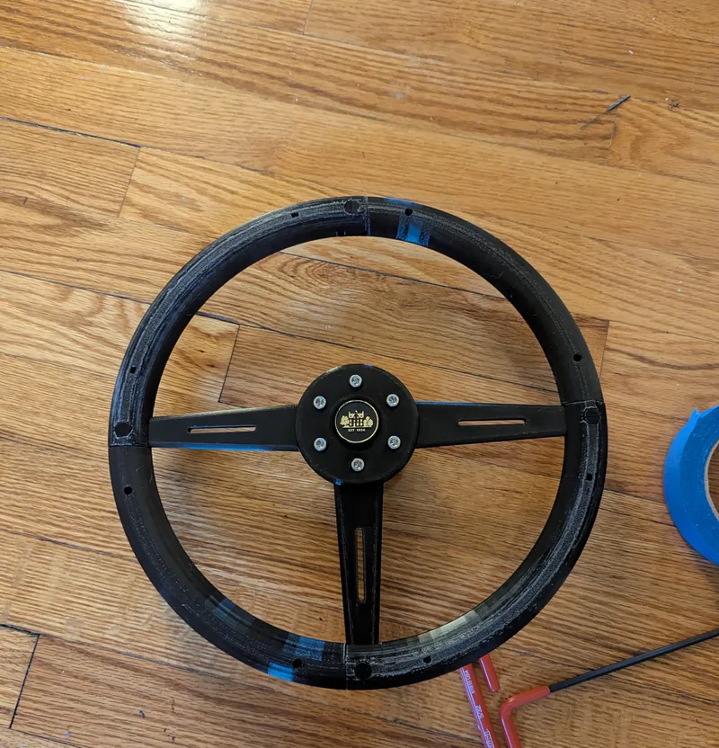
The first design converted it into a shaft-driven motor: I faced off the housing, pressed out the shaft and machined a replacement in 316 stainless. That damaged the bearings and put chips in the magnets, and the motor bound. So the second design leaves the motor untouched.
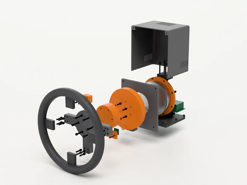
A clamp in the hub's outer groove drives the wheel on friction and bolt load, which SOLIDWORKS FEA confirmed for the roughly 12 Nm output. It carries a higher moment, so the mounting had to be stronger.
Printed structure, machined where it counts
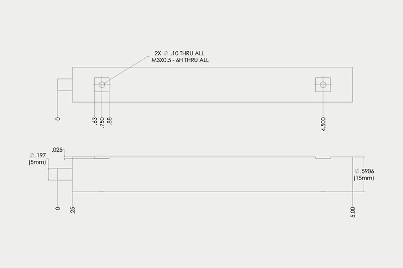
An aluminum coupler clamps the motor shaft on its flat and bolts to a support plate. Most of the structure is 3D printed, and only the high-load parts are machined from aluminum. Power comes from a 24 V supply salvaged from a broken Ender 3, driving an ODESC flashed with the open-source FFBeast firmware.
With no way to center a magnet on the sealed motor, a 6:1 GT2 belt with an idler carries position to a separate standoff pulley holding the magnet and encoder.
Direct drive, and a third design in CAD
The second design gives real direct-drive force feedback for about $100, with electronics and purchased parts as the only real expense.
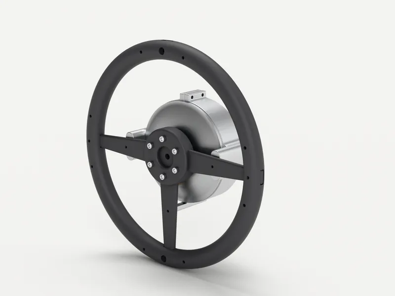
The third design, in CAD now, turns it into a finished product around the same sealed motor: a hub that clamps the 138 mm lip from both sides, 120 GT2 teeth printed directly on the hub nose, an MT6701 encoder in a sliding pod, and a one-piece cover over the electronics.
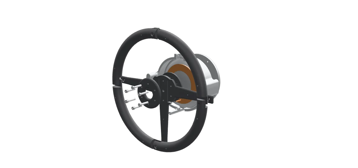
Parts list
- Alloy steel socket-head screw× 5
- Aluminum extrusion rail× 2
- Rear spacer
- Front cross member× 2
- Front base cross member
- Ball bearing
- Face coupling, rotor side
- Hub motor can (rotor)
- Stator and windings
- Motor mount
- Rotor shaft coupling
- Custom 316 SS shaft
- 316 SS socket-head screw× 6
- Face coupling, wheel side
- Rim quarter× 4
- Hub plate, front
- Top-center plug
- Side spoke× 2
- Vertical spoke
- 24 V power supply
- Side frame
- Rim-groove clamp× 2
- Hub motor can (rotor)
- Stator and windings
- Rotor shaft coupling
- 316 SS socket-head screw× 6
- Rim quarter× 4
- Hub plate, front
- Top-center plug
- Side spoke× 2
- Vertical spoke
- Hub plate, rear
- Socket-head screw× 42
- M5 hex nut× 4
- Hub motor can (rotor)
- Stator and windings
- Motor rear cover and shaft
- Chassis (base and tower)
- Shaft clamp cap
- Hub body
- Clamp ring half× 2
- Hub nose, 120T GT2
- Front panel
- Encoder housing
- Encoder lid
- Magnet holder
- One-piece cover
- Three-spoke wheel core
- Rim quarter× 4
- Top marker
- Flipsky ODESC V4.2
- MT6701 encoder board
- GT2 20T pulley
- GT2 belt, 300 mm closed
- 625-2RS bearing× 2
- Encoder shaft, 5 mm
- Diametric magnet
- Brake resistor, 50 W